

Newspaper „Ordinea” – 29 Aug. 1936
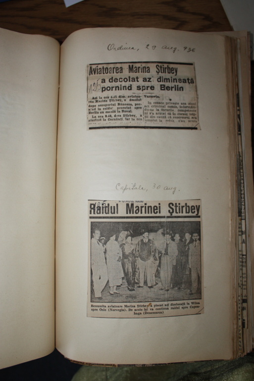
Newspaper „Ordinea” – 29 Aug. 1936 Female aviator Marina Știrbey took-off this morning towards Berlin During the flight she will stop in Cernăuți and in Warsaw [tabs] [tab title=”Original Document”][singlepic id=566 w=320 h=240 float=none][/tab] [tab title=”Pilots mentioned”][recent_posts count=”100″ cat=”124″][/tab] [/tabs]
Newspaper „Credinţa” – 27 May 1936
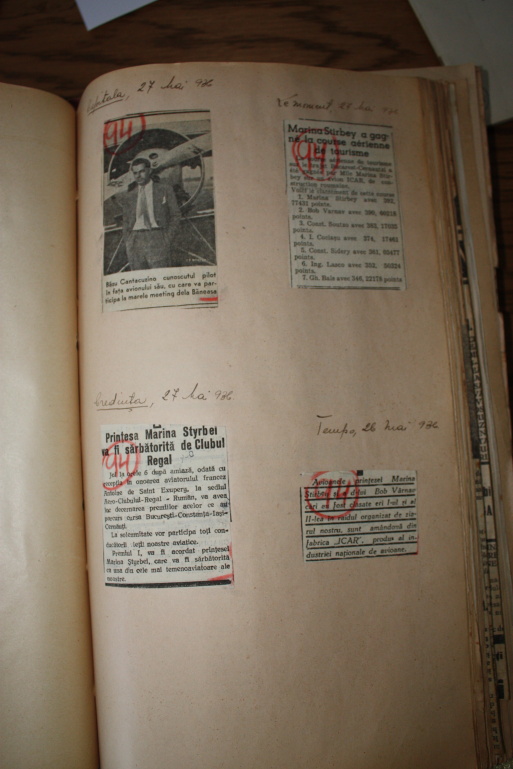
Newspaper „Credinţa” – 27 May 1936 Princess Marina Știrbey will be celebrate by the Royal Club During a reception given in honour of French aviator Antoine de Saint-Exupéry princess Marina Știrbey will receive First place award for participating the journey on the route Bucharest-Cernăuți [tabs] [tab title=”Original Document”][singlepic id=567 w=320 h=240 float=none][/tab] [tab title=”Pilots mentioned”][recent_posts count=”100″ cat=”130″][/tab] [/tabs]
Newspaper „Tempo” – 26 May 1936
Newspaper „Tempo” – 26 May 19366 The planes piloted by Marina Ştirbey and Bob Vârnav have been fabricated at the ICAR factory in Romania. [tabs] [tab title=”Original Document”][singlepic id=567 w=320 h=240 float=none][/tab] [tab title=”Pilots mentioned”][recent_posts count=”100″ cat=”130″][/tab] [/tabs]
Miles M.2 Hawk Trainer
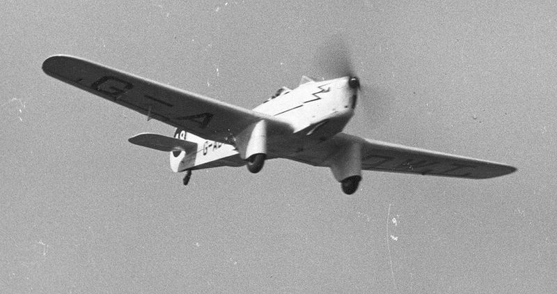
[tabs] [tab title=”Brief”] Miles M.2 Hawk Trainer The Miles Hawk Trainer was a 1930s British two-seat training monoplane designed by Miles Aircraft Limited. About Miles M.2 Hawk Trainer – Source Wikipedia Role: Two-seat touring and racing monoplane Manufacturer: Miles Aircraft Limited Designer: Frederick George Miles First flight: 1935 Primary users: Royal Air Force, Romanian Air Force Number built: 27
MiG 3 (Mikoyan-Gurevich 3)
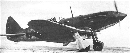
[tabs] [tab title=”Brief”] MiG 3 (Mikoyan-Gurevich 3) The Mikoyan-Gurevich 3 (MiG-3) was a Soviet fighter aircraft used during World War II. About MiG 3 (Mikoyan-Gurevich 3) – Source Wikipedia Role: Fighter National origin: Soviet Union Manufacturer: Mikoyan – Gurevich Designers: Artem Mikoyan and Mikhail Gurevich First flight: 29 October 1940 Introduction: 1941 Status: Retired in 1945 Primary users: Soviet Air Forces, Soviet Air Defence Forces, Soviet Naval Aviation Number built: 3,172 Developed from: Mikoyan-Gurevich MiG-1 Variants: Mikoyan-Gurevich I-211 Specifications (MiG – 3) Data from MiG: Fifty Years of Secret Aircraft Design General characteristics Crew: One Length: 8.25 m (27 ft 1 in) Wingspan: 10.20 m (33 ft 5 in) Height: 3.30 m (10 ft 9⅞ in) Wing area: 17.44 m² (188 ft²) Airfoil: Clark YH Empty weight: 2,699 kg (5,965 lb) Loaded weight: 3,355 kg (7,415 lb) Powerplant: × Mikulin AM-35A liquid-cooled V-12, 993 kW (1,350 hp) Performance Maximum speed: 640 km/h (398 mph, 346 knots) at 7,800 m (25,600 ft) Maximum speed at sea level: 505 km/h (314 mph, 273 knots) Combat range: 820 km (510 mi,443 NM) Service ceiling: 12,000 m (39,400 ft) Wing loading: 155 kg/m² (39.3 lb/ft²) Power/mass: 0.30 kW/kg (0.18 hp/lb) Climb to 8 000 m (26 250 ft): 10.28 Armament 1 × 12.7 mm UBS machine gun 2 × 7.62 mm ShKAS machine guns 2 × 100 kg (220 lb) bombs, 2 spray containers for chemicals, gas or flammable liquids or 6 × 82 mm RS-82 rockets [/tab] [tab title=”Detailed information”] MiG 3 (Mikoyan-Gurevich 3) The Mikoyan-Gurevich 3 (MiG-3) was a Soviet fighter aircraft used during World War II. The Mikoyan-Gurevich MiG-3 (Russian: Микоян и Гуревич МиГ-3) was a Soviet fighter aircraft used during World War II. It was a development of the MiG-1 by the OKO (opytno-konstrooktorskiy otdel — Experimental Design Department) of Zavod (Factory) No. 1 to remedy problems that had been found during the MiG-1’s development and operations. It replaced the MiG-1 on the production line at Factory No. 1 on 20 December 1940 and was built in large numbers during 1941 before Factory No. 1 was converted to build the Ilyushin Il-2. On 22 June 1941 at the beginning of Operation Barbarossa, some 981 were in service with the VVS, the PVO and Naval Aviation. The MiG-3 was difficult to fly in peacetime and much more so in combat. It had been designed for high-altitude combat but combat over the Eastern Front was generally at lower altitudes where it was inferior to the German Messerschmitt Bf 109 as well as most modern Soviet fighters. It was also pressed into service as a fighter-bomber during the autumn of 1941 but it was equally unsuited for this. Over time the survivors were concentrated in the PVO, where its disadvantages mattered less, the last being withdrawn from service before the end of the war. Development The large number of defects noted during flight testing of the MiG-1 forced Mikoyan and Gurevich to make a number of modifications to the design. Testing was done on a full-size aircraft in the T-1 wind tunnel belonging to the Central Aero and Hydrodynamics Institute (TsAGI) to evaluate the problems and their proposed solutions. The first aircraft to see all of these changes applied was the fourth prototype of the I-200. It first flew on 29 October 1940 and was approved for production after passing its State acceptance trials. The first MiG-3 as the improved aircraft was named on 9 December, was completed on 20 December 1940 and another 20 were delivered by the end of the year. These changes included:: The engine was moved forward 100 mm (4 in) to improve longitudinal stability. A new water radiator (OP-310) was fitted. The first two modifications which allowed an additional 250 litres (66 US gal) fuel tank to be fitted underneath the pilot’s seat. The outer wingpanel dihedral was increased by one degree to increase longitudinal stability. An additional oil tank was mounted under the engine. Piping was fitted to use cooled inert exhaust gasses in the fuel tanks to reduce the chance of fire. The back of the pilot’s seat was armored with a 8 mm (0.31 in) plate (increased to 9 mm (0.35 in) in later models). The supercharger intakes were streamlined. The main landing gear was strengthened and the size of the main wheels was increased to 650 x 200 mm (25.5 x 7.87 in). The canopy glazing was extended aft to improve the view to the rear which allowed for the installation of a shelf behind the pilot for an RSI-1 radio (later upgraded to an RSI-4). The instrument panel layout was improved and a PBP-1A gunsight replaced the original PBP-1. Ammunition for the ShKAS guns was increased to 750 rounds per gun. Two additional underwing hardpoints were added to carry up to 220 kg (485 lb) of bombs, spray containers or RS-82 rockets. State acceptance testing of two production aircraft was conducted between 27 January and 26 February 1941. They were found to be over 250 kg (550 lb) heavier than the MiG-1, which reduced maneuverability and field performance. Time to 5,000 m (16,000 ft) decreased by over a minute and the service ceiling proved to be 500 m (1,600 ft) less. The MiG-3 was faster at sea level and at height. While the ranges reached by both aircraft were farther than that of the older aircraft, they were still less than the 1,000 km (620 mi) required. Mikoyan and Gurevich protested against the range results as their calculations showed that the MiG-3 could reach 1,010 km (630 mi) based on a specific fuel consumption (SFC) of 0.46 kg/km (1.64 lb/mile). During the State acceptance trials the SFC was 0.48 kg/km (1.71 lb/mile) but the operational trials conducted earlier showed a SFC of 0.38 kg/km (1.35 lb/mile). They blamed the deficiency on a failure to use an altitude correction and that the engines had not been properly adjusted. They went as far as arranging for two more flights between Leningrad and Moscow to prove the MiG-3 could fly 1,000 km (621 mi). Two production aircraft were flown to ranges of 1,100 km (680 mi) and 971 km (603 mi), flying at 90% of maximum speed and at an altitude of 7,300 m (24,000 ft), contradicting the report of the NII VVS (Naoochno-Issledovatel’skiy Institoot Voyenno-Vozdooshnykh
BFW M.26
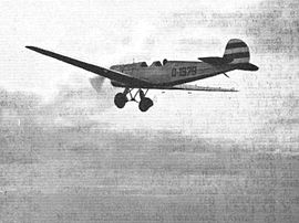
[tabs] [tab title=”Brief”] BFW M.26 The BFW M.26 was a single-engined cantilever-winged monoplane light airliner built in Germany in 1930. About BFW M.26 – Source Wikipedia Role: Light airliner National origin: Germany Manufacturer: Bayerische Flugzeugwerke (BFW) Designer: Willy Messerschmitt First flight: 1930 Number built: 1 Specifications (BFW M.26) Data from Smith 1971, p. 28 General characteristics Crew: One Capacity: 2/6 passengers Length: 7.15 m (23 ft 5½ in) Wingspan: 1.40 m (40 ft 8¼ in) Height: 2.30 m (7 ft 6½ in) Empty weight: 460 kg (1,014 lb) Gross weight: 700 kg (1,543 lb) Powerplant: 1 × Siemens Sh 11 7-cylinder radial engine, 75 kW (100 hp) [/tab] [tab title=”Detailed information”] BFW M.26 The BFW M.26 was a single-engined cantilever-winged monoplane light airliner built in Germany in 1930. Design and development The BFW M.26 was a light civil aircraft designed to carry two to three passengers in an enclosed cabin. The pilot’s position was also enclosed. It was a high cantilever winged monoplane in the style of Messerschmitt’s earlier three cabin aircraft, the successful BFW M.18 and BFW M.20 and the commercially unsuccessful BFW M.24, though smaller than any of them. A typical Messerschmitt square section fuselage narrowed steadily to the tail with its very angular fin and rudder. The latter was cut away at the base to allow for the movement of the single piece elevator. The main undercarriage was of the split axle type. The M.26 was powered by a 100 hp (45 kW) Siemens Sh 11 radial engine, mounted uncowled with the seven cylinder heads protruding for cooling. It drove a two-bladed propeller. The aircraft first flew in 1930, but no production ensued and only one M.26 was built. A version with a 175 hp (130 kW) Wright Whirlwind was considered under the designation M.30, but not built. [/tab] [tab title=”Gallery”] BFW M.26 The BFW M.26 was a single-engined cantilever-winged monoplane light airliner built in Germany in 1930. [nggallery id=31] [/tab] [tab title=”Pilots”] BFW M.26 The BFW M.26 was a single-engined cantilever-winged monoplane light airliner built in Germany in 1930. [recent_posts count=”100″ cat=”56″] [/tab] [/tabs]
Klemm Daimler L.20
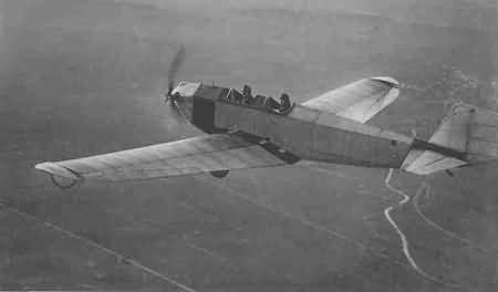
[tabs] [tab title=”Brief”] Klemm Daimler L.20 Aircraft designed by Dr.-Ing. Hanns Klemm held a special position in the flight training in Germany in the mid-twenties. About Klemm Daimler L.20 – Source Wikipedia Role: Two seat light aircraft National origin: Germany Manufacturer: Daimler aircraft and Klemm Flugzeugebau Designer: Hans Klemm First flight: 1924 Variants: Klemm KL.25 Specifications (Klemm Daimler L.20) Data from General – Flight 1927; Performance – Deutches Museum Archive General characteristics Crew: Two Wingspan: 13.0 m (42 ft 8 in) Wing area: 20.0 m2 (215 sq ft) Empty weight: 265 kg (584 lb) Gross weight: 265 kg (584 lb) Wing loading: 22.5 kg/m2(4.60 lb/sqft) Powerplant: 1 × Mercedes F7502a 885 cc, air-cooled flat twin, 15 kW (20 hp) 20 PS Propellers: 2-bladed Power loading: 30 kg/kW (50 lb/hp) Performance Maximum speed: 105 km/h (65 mph; 57 kn) Range: 480 km (298 mi; 259 nmi) Service ceiling: 4,100 m (13,451 ft) Time to altitude: 12.6 min to 1,000 m (3,281 ft) Landing speed: 42 km/h (26 mph) [/tab] [tab title=”Detailed information”] Klemm Daimler L.20 Aircraft designed by Dr.-Ing. Hanns Klemm held a special position in the flight training in Germany in the mid-twenties. Design and development Hans Klemm’s first light aircraft was the Daimler L15 and the L20 had much in common with it. Both were cantilever monoplanes with twin open, tandem cockpits and engines of very low power. The L20’s low wing distinguished it from its predecessor and had advantages of providing a low centre of gravity and better views during the landing approach as well as better protection for occupants in the case of crash landings. The low set wing also allowed a shorter undercarriage on the L20, which was otherwise like that of the L15 with the wheels independently mounted on pairs of centrally hinged V-struts and with vertical shock absorbing legs to the wing underside. Wheels were sometimes replaced by floats. Intended from the start for serial production, the L20’s structure was simplified, with a pentagonal cross-section fuselage lacking the L15’s rounded upper and lower surfaces. The fuselage was wooden framed with canvas covering. The overall strength of the structure, which had a safety factor of 12, was emphasised. The wing was tapered in plan and was built around two spars, though there were two variants of the internal wing structure. The first three aircraft, type L20 A1, had wings stiffened against torsion by internal wire bracing but later aircraft, type L20 B1, used a torsion box formed by plywood skin ahead of the rear spar. Like the later version of the L15, the L20 used a combination of conventional ailerons and unusual wing tip flaps, rotating about an axis well ahead of mid-chord. The ailerons were directly controlled from the cockpit as normal and the tip flaps were linked to them with external rods and cranks. On early examples these flaps were roughly square, with a side less than a half of the chord at the tip, but at some later time they were reshaped to produce wing curved tips. The wings could be detached at the root in about 5 minutes, reducing the width of the L20 to 1.7 m (67 in) for road transport on a trailer pulled by a car. At the beginning of the design and testing period the absence of a suitable, serially produced light aircraft engine was a concern and the wing was therefore mounted so that it could be moved fore and aft to allow for the varying centre of gravity positions resulting from engines of different weight. A glider version was contemplated though not used in the end. Instead, the flight programme began with the L20 powered by the 9 kW (12.5 hp) Harley-Davidson motor cycle engine used in the L15. By mid 1925 this had been replaced with a new engine, the 15 kW (20 hp) air-cooled, flat twin Mercedes F7502a, which Klemm had persuaded Daimler’s engine group to design and build for the light aircraft market. The cost of flying the L20 were low as its cruise fuel consumption was only 63 mL/km (45 mpg). From 1926 the uprated 15 kW (20 hp) Mercedes F7502b was fitted. The F7502 was central to the success of the L20, though it suffered from repeated rocker arm failures. Having failed to persuade the Daimler management to undertake series production of the L20 despite its early successes, in 1927 Klemm left to set up his own company, Klemm Light Aircraft in Sindelfingen, later moving to Böblingen. Thereafter the L20 was often known as the Klemm-Daimler L20 or sometimes the Daimler-Klemm L20. After 1926, new designs appeared under Klemm’s name alone; for example the Klemm L25, later Kl25, was a revision of the L20 with a 15 kW (20 hp) Salmson radial engine. Operational history The 1925 Round Germany Flight involved five circuits over a total distance of 5,262 km (3,270 mi). Two early L20s and the twin engined L21 competed against many aircraft from other German manufacturers. All three Daimler aircraft were very successful in the under 40 hp (30 kW) class, with the L21 the overall winner, receiving 25,000 Goldmarks (worth £1,250 in 1925) and the two L20’s coming second and third and winning another 25,000 Goldmark between them. They also contributed to the award of first prize in the contest between German engined aircraft to Mercedes. L 20 at the Zeller See after crossing the Alps in winter The best known and most significant flight by the L20 was the wintertime crossing of the Alps in early 1926. Flight Magazine hailed this as the „Vindication of the Light ‘Plane”, in the sense that it showed small aircraft to be a practical vehicle for travel over difficult terrain and in uncertain weather. The pilot was Guritzer and the navigator/engineer von Lansdorff, both from Daimler. The flight began at Daimler’s Sindelfingen base on 16 February. No special preparation such as fuel dumps were made in advance and carefully prepared maps were lost overboard early in the flight. The weather frustrated several attempts to cross the Alps but at last
Klemm KI 25
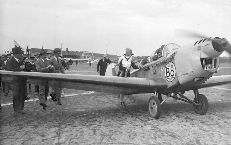
[tabs] [tab title=”Brief”] Klemm Kl 25 Klemm L.25, later Klemm Kl 25 was a successful German light leisure, sports and training monoplane aircraft, developed in 1928. About Klemm Kl 25 – Source Wikipedia Role: Training plane Manufacturer: Klemm First flight: 1928 Specifications (L 25 d VII R) General characteristics Length: 7.5 m (24 ft 7 in) Wingspan: 13.0 m (42 ft 8 in) Height: 2.05 m (6 ft 9 in) Wing area: 20.0 m² (215 sq ft) Empty weight: 420 kg (926 lb) Max. takeoff weight: 720 kg (1,587 lb) Performance Maximum speed: 160 km/h (99 mph, 86 kn) Range: 650 km (404 mi) Service ceiling: 4,800 m (15,748 ft) [/tab] [tab title=”Detailed information”] Klemm Kl 25 Klemm L.25, later Klemm Kl 25 was a successful German light leisure, sports and training monoplane aircraft, developed in 1928. Klemm L.25, later Klemm Kl 25 was a successful German light leisure, sports and training monoplane aircraft, developed in 1928. More than 600 aircraft were built, and manufacturing licenses were sold to the United Kingdom and the United States. Design and construction With low cantilever wing, fixed landing gear, and two open cockpits,[1] the aircraft was developed by Hanns Klemm who used his previous design, the Klemm Kl 20, as a starting point. It first flew on a 20 hp (15 kW) Mercedes engine.[1] About thirty different versions of the Kl 25 were made, and these were equipped with engines ranging from 32 to 70 kW (43 to 94 hp). The fuselage was covered with plywood. Depending on the model, the aircraft’s weight was 620 to 720 kg (1,367 to 1,587 lb), and it had a 10.5 to 13 m (34 to 43 ft) wingspan. Take-off was achieved at only 50 km/h (31 mph) and the maximum speed was between 150 to 160 km/h (93 to 99 mph). In relation to similar aircraft of the time, assembly was very easy, and this made it a very popular aircraft. According to the sales brochures, only 25% of the engine’s power was needed to keep the aircraft flying, compared to biplanes of the period, which required 50% engine power. About 600 were built in Germany between 1929 and 1936,[1] serving with various flight training organizations, on either wheels, skis, or floats.[1] Fifteen were sold to Britain before the Second World War,[1] being fitted with a variety of domestic engines,[1] while twenty-eight more were built by British Klemm Aeroplane Company as the B.A. Swallow.[1] Production in the United States was carried out by the Aeromarine-Klemm Company which enjoyed moderate success as well as developing models for the American market in isolation from the parent company, with about 120 built of all models. Variants NB, list not complete Germany L 25 a: Built between 1927 and 1929, equipped with a Daimler F 7502 engine (22 PS) L 25 I, Ia and IW: Built between 1928 and 1929, equipped with a Salmson AD.9 engine (45 PS) L 25 b: Built in 1931, equipped with a 22 PS Daimler engine L 25 b VII: Built in 1931, equipped with a Hirth HM 60 engine (60 PS) L 25 d II: Built in 1933, equipped with a Siemens Sh 13 a engine (88 PS) L 25 d VII: Equipped with a Hirth HM 60 R engine (80 PS) L 25 IVa: Equipped with Armstrong Siddeley Genet engine L 25E or Ve: pecial competition variant (E for Europa Rundflug 1930), with a closed canopy, smaller span, equipped with Argus As 8 straight engine (103 PS / 75.7 kW) VL 25 Va: VL 25 Va: Three-seater variant, with a closed canopy, equipped with Argus As 8 straight engine (103 PS / 75.7 kW) United Kingdom British Klemm Aeroplane Company B.K. Swallow British Aircraft Manufacturing Co. B.A. Swallow II United States Aeromarine-Klemm AKL-25 Aeromarine-Klemm AKL-26 Aeromarine-Klemm AKL-27 Aeromarine-Klemm AKL-60 Aeromarine-Klemm AKL-70 Aeromarine-Klemm Model 70 Trainer [/tab] [tab title=”Gallery”] Klemm Kl 25 Klemm L.25, later Klemm Kl 25 was a successful German light leisure, sports and training monoplane aircraft, developed in 1928. [nggallery id=25][/tab] [tab title=”Pilots”] Klemm Kl 25 Klemm L.25, later Klemm Kl 25 was a successful German light leisure, sports and training monoplane aircraft, developed in 1928. [recent_posts count=”100″ cat=”50″][/tab] [/tabs]
Klemm Kl 35
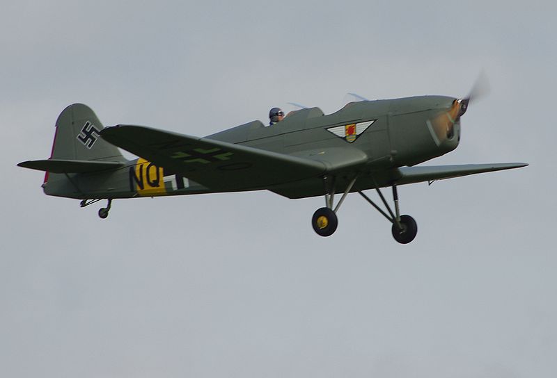
[tabs] [tab title=”Brief”] Klemm Kl 35 The Klemm Kl 35 was a German sporting and training aeroplane developed as a successor to the Klemm Kl 25. About Klemm Kl 35 – Source Wikipedia Role: Two-seat sports and training aircraft Manufacturer: Klemm Leightflugzeugbau Gmbh Designer: Friedrich Fecher First flight: 1935 Introduction: 1935 Status: Out of service Primary users: Luftwaffe, Czechoslovakia, Hungary, Romania, Sweden Produced: 1937 – 1944 Number built: 2000 Unit cost: RM 17 500 Specifications (Klemm Kl 35D) Data from The Concise Guide to Axis Aircraft of World War II General characteristics Crew: Two Length: 7.50 m (24 ft 7¼ in) Wingspan: 10.40 m (34 ft 1¼ in) Height: 2.05 m (6 ft 8¾ in) Wing area: 15.20 m² (163.62 ft²) Empty weight: 460 kg (1,014 lb) Max. takeoff weight: 750 kg (1,654 lb) Powerplant: 1 × Hirth HM 60R 4-cylinder inverted inline engine, 60 kW (80 hp) Performance Maximum speed: 212 km/h (132 mph) Cruise speed: 190 km/h (118 mph) Range: 665 km (413 mi) Service ceiling: 4,350 m (14,270 ft) [/tab] [tab title=”Detailed information”] Klemm Kl 35 The Klemm Kl 35 was a German sporting and training aeroplane developed as a successor to the Klemm Kl 25. The Klemm Kl 35 was a German sporting and training aeroplane developed as a successor to the Kl 25. A product of Klemm Leichtflugzeugbau Gmbh it shared the same single-engine, cantilever low-wing configuration as the earlier machine, the major difference being the introduction of an inverted gull wing. Probably Klemm’s most important type, the fully aerobatic aeroplane was shown for the first time publicly in October 1935 at the international Air Show in Milan and soon found many private buyers. Powered initially by an 80 hp (60 kW) Hirth HM60R inline, it had fixed undercarriage, mixed wood and fabric covering, and the choice of open or closed cockpit. Powered by the Hirth 60R, it became the Kl 35A (with floats, Kl 35AW), while with the 105 hp (78 kW) Hirth, it was the Kl 35A (with floats, Kl 35AW). An improved Kl 35D, designed as a Luftwaffe trainer, with 105 hp (78 kW) Hirth HM 504A-2 engine and the option of ski or float landing gear, appeared in 1938. It was the most numerous, with over three thousand built. A number of air forces purchased copies, including the Romanian, Hungarian, and Slovak. The Flygvapnet bought several, designated Sk 15, for training use (at least five of those seaplanes) and in 1941 began licence production, building about 74 more, some surviving in service until 1951. The Lithuanian Aircraft Platoon flew three. Development The Kl 35 was designed in 1934 under the auspices of the Reichsluftfahrtministerium (RLM). Dipl. Ing. Friedrich Fecher had overall responsibility for the construction. The so-called Gemischtbauweise construction was used: steel for fuselage, wood for wings and tail units and only small quantities of light alloy for linings were used. This became a preferred building method with the RLM around this time, because from considerations of strategic material availability. Production The results of the trial must have been satisfactory, because in July 1936, 23 aircraft were ordered for delivery between July and September 1937, with production planned to increase to 3 per month. Klemm was at the time manufacturing the Fw 44 under licence from Focke-Wulf. By this time the RLM was already looking for a sub-contractor to build the Kl 35A under licence, choosing Fieseler which was already undertaking licence production of the He 72 and Fw 58 alongside Storchs at its Kasseler plant. Further orders, to a total of 1,386, followed and new variants came on line, beginning with the Kl 35B with a new engine. Manufacture at Fieseler ceased in November 1939, after 365 aircraft, when the RLM transferred licence production to Zlin in occupied Czechoslovakia. Production ended in May 1943 with total production for the Luftwaffe having reached 1,302. The balance of production was for private and export customers, though since these would have to number nearly 700 to reach the oft-quoted total of around 2,000 this may be exaggerated. Variants Kl 35a – The first prototype, powered by a 60-kW (80-hp) Hirth HM60R piston engine. Kl 35b – Second prototype. Kl 35B – Initial production version, powered by a 60-kW (80-hp) Hirth RM60R piston engine. Kl 35BW – Floatplane version. Kl 35D – Improved version, fitted with a tricycle undercarriage. Kl 106 – version of the Kl 35D with Hirth HM 500 engine intended for production under licence in the United States Survivors Klemm Kl35 No Luftwaffe machine is known to survive, but a number of ex-Flygvapnet machines have been preserved. Klemm Kl 35D G-KLEM is owned and operated by Peter Holloway at Old Warden, Bedfordshire, UK. Klemm Kl 35D SE-BGA flew again after nearly 50 years on 19 December 2009. It is based at Håtuna, near Stockholm. [/tab] [tab title=”Gallery”] Klemm Kl 35 The Klemm Kl 35 was a German sporting and training aeroplane developed as a successor to the Klemm Kl 25. [nggallery id=24][/tab] [tab title=”Pilots”] Klemm Kl 35 The Klemm Kl 35 was a German sporting and training aeroplane developed as a successor to the Klemm Kl 25. [recent_posts count=”100″ cat=”49″][/tab] [/tabs]
Junkers Ju 86
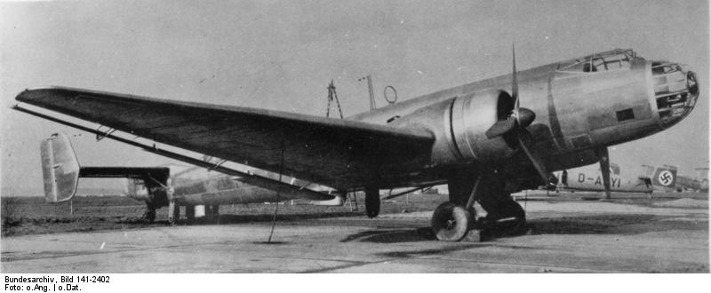
[tabs] [tab title=”Brief”] Junkers Ju 86 The Junkers Ju 86 was a German monoplane bomber and civilian airliner designed in the early 1930s, and employed by both sides during World War II. About Junkers Ju 86 – Source Wikipedia Role: Bomber, Airliner, Reconnaissance aircraft Manufacturer: Junkers First flight: 1934 Introduction: 1936 Status: Retired Primary user: German Luftwaffe Specifications (Junkers Ju 86) Data from Jane’s Fighting Aircraft of World War II and Warbirds Resource Group General characteristics Crew: Two (pilot and radio operator) Length: 16.46 m (54 ft) Wingspan: 32 m (105 ft) Height: 4.7 m (15 ft 5 in) Wing area: 82 m² (883 ft²) Empty weight: 6,700 kg (14,800 lb) Max. takeoff weight: 11,530 kg (25,420 lb) Powerplant: 2 × Junkers Jumo 207B-3/V diesel engines, 746 kW (1,000 hp) each Performance Maximum speed: 420 km/h (260 mph) above 9,150 m (30,000 ft) Range: 1,580 km (980 mi) Service ceiling: 13,000 m (42,650 ft) Rate of climb: 4.67 m/s (900 ft/min) Armament Guns: defensive armament of three MG 15 machine guns Bombs: 1,000 kg (2,200 lb) of bombs [/tab] [tab title=”Detailed information”] Junkers Ju 86 The Junkers Ju 86 was a German monoplane bomber and civilian airliner designed in the early 1930s, and employed by both sides during World War II. The Junkers Ju 86 was a German monoplane bomber and civilian airliner designed in the early 1930s, and employed by both sides during World War II. The civilian model Ju 86B could carry 10 passengers. Two were delivered to Swissair and five to Luft Hansa. In addition a single civilian Ju 86Z was delivered to the Swedish AB Aerotransport. Design and development In 1934, a specification for a modern twin-engined aircraft capable of operating both as a high speed airliner for the German airline Luft Hansa and as a medium bomber for the still-secret Luftwaffe was issued to both Junkers and Heinkel. Five prototypes were ordered from each company; the Junkers Ju 86 and Heinkel He 111. Junkers’ design was a low-winged twin engined monoplane, of all-metal stressed skin construction. Unlike most of Junkers’ previous designs, it discarded their typical corrugated skinning in favour of smooth metal skinning which helped to reduce drag. The craft was fitted with a narrow track retractable tailwheel undercarriage and twin fins and rudders. It was intended to be powered by the Junkers Jumo 205 diesel engines, which although heavy, gave better fuel consumption than conventional petrol engines. The bomber aircraft had a crew of four; a pilot, navigator, radio operator/bombadier and gunner. Defensive armament consisted of three machine guns, situated at the nose, at a dorsal position and within a retractable ventral position. Bombs were carried vertically in four fuselage cells behind the cockpit. The airliner version replaced the bombload with seating for 10 passengers, with fuel tanks being moved from the fuselage to the wings. The first prototype Ju 86, the Ju 86ab1, fitted with Siemens SAM 22 radial engines as airworthy Jumo 205s were unavailable, flew on 4 November 1934, in bomber configuration, with the second prototype, also a bomber, flying in January 1935. The third Ju 86, and the first civil prototype, flew on 4 April 1935. Production of pre-series military and civil aircraft started in late 1935, with full production of the Ju 86A-1 bomber commencing in April 1936. Production quickly switched to the improved Ju 86 D with a modified tail cone to improve stability. Early use of the Jumo powered Ju 86 bomber over Spain showed that it was inferior to the He 111, with the diesel engines being unsuitable for rough treatment during combat, and production plans were cut back. One Ju 86 had already been converted to use radial engines as a testbed for possible export versions, and this showed much improved reliability. With production switched to a version powered by the BMW 132 engine, the Ju 86E; production continuing until 1938. The „Z” designation suffix for civil variants, introduced in 1936, was allocated to three models: the Jumo-engined Z-1 (corresponding to the former B-0 or C-1), sold to Swissair (one), Airlines of Australia (one), and LAN-Chile (three); the BMW 132H-powered Z-2 for DLH (two) and the para-military Manchukuo Air Transport (five or more); and the Hornet-engined Z-7, delivered to AB Aerotransport of Sweden (one, for use on mail services), Lloyd Aereo Boliviano (three), and South African Airways (17). The ABA aircraft was later transferred to the Swedish Air Force, with which it served, under the designation Tp 9, until 1958. SAA’s original intention was to have its Ju 86s powered by 745 hp Rolls-Royce Kestrels. Six aircraft for SAA, flown with these engines, were refitted with Hornets before delivery, and the remainder were also Hornet-powered. The Ju 86 was sold to airlines and air forces from several nations, including Bolivia, Chile, Hungary, Manchukuo, Portugal, the South African Air Force (SAAF), Spain, and Sweden. The Ju 86K was an export model, also built under license in Sweden by Saab as the B 3 with (905 hp) Bristol Mercury XIX radial engines. Several aircraft remained in service with the Swedish Air Force until 1958. A few were converted to SIGINT platforms. Operational history The bomber was field tested in the Spanish Civil War, where it proved inferior to the Heinkel He 111. Four Ju 86D-1s arrived in Spain in early February 1937, but after a few sorties one of them (coded 26-1) was shot down on 23 February by Republican fighters with the loss of three crewmen killed and one captured. A replacement aircraft was sent from Germany, but in the summer of 1937 another D-1 was lost in an accident, and the three remaining aircraft were sold to the Nationalist air forces. It was again used in the 1939 invasion of Poland, but retired soon after. In January 1940, the Luftwaffe tested the prototype Ju 86P with a longer wingspan, pressurized cabin, Jumo 207A1 turbocharged diesel engines, and a two-man crew. The Ju 86P could fly at heights of 12,000 m (39,000 ft) and higher on occasion, where it was felt to be safe from Allied fighters. The British Westland